FCSys
![]()
Table of Contents
- User's Guide
- Blocks
- Conditions
- Assemblies
- Regions
- Subregions
- Phases
- Species
- Chemistry
- Connectors
- Characteristics
- Units
- Quantities
- Utilities
- Icons
Download
- Latest: v0.2.6 (2014-01-25)
Search
FCSys
Modelica fuel cell libraryInformation
FCSys is a free, open-source library of equation-based, object-oriented (EOO) models of proton exchange membrane fuel cells (PEMFCs) in the Modelica language. The models are:
- Dynamic
- Multi-domain: Chemical, electrical, fluid, and thermal phenomena are included.
- Multi-phase: Water is included and transported independently as vapor, liquid, and absorbed in the ionomer. Phase change is represented as a dynamic process.
- Multi-dimensional
- Highly reconfigurable: There are options to adjust the assumptions, dimensionality (1D, 2D, or 3D), and spatial discretization (i.e., resolution). Species may be independently enabled at instantiation, unlike the Modelica media library. The framework is generic and can be extended to other fluidic or electrochemical devices like batteries.
- Highly modular: Each layer of the cell is a separate model which is hierarchically constructed from graphical models of subregions, phases, and species. At each level, EOO (i.e., effort/flow) connectors are used to combine the various components.
- Fully declarative: There are no causal connectors besides those used to apply boundary conditions. Functions are only used to simplify subexpressions of equations.
- Physics-based: The equations are based on first principles, with explicit conservation of material, momentum, and energy in every control volume and across every interface. A unique and physically appropriate method of upstream discretization is used to describe coupled advective and diffusive transfer. All physical quantities are mapped to universal physical constants using a novel, flexible implementation of natural units.
- Computationally efficient: There are minimal switching events and no nonlinear systems of equations after appropriate translation. A typical polarization curve can be simulated in less than two seconds.
Figure 1 shows the seven primary layers of a typical PEMFC, which are also the components of the fuel cell model shown in Figure 2. Fluid enters and exits the cell through channels in the flow plates (FPs). It spreads through the gas diffusion diffusion layers (GDLs) and reacts in the catalyst layers (CLs) according to the following electrochemical equations:
| 2(H2 | → | 2e- + 2H+) | (anode) |
| 4e- + 4H+ + O2 | → | 2H2O | (cathode) |
|
|
|||
| 2H2 + O2 | → | 2H2O | (net) |
The proton exchange membrane (PEM) prevents electronic transport; therefore, electrons must pass through an external load to sustain the net reaction.
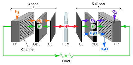
Figure 1: Layers and primary flows of a PEMFC.
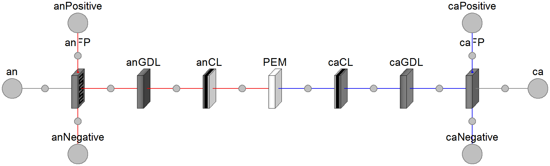
Figure 2: Diagram of the PEMFC model.
The fuel cell model can be exercised using the test stand shown in Figure 3 or connected to the Modelica fluid library using available adapters. Please see the sample cell results for examples and the getting started page for information about using the library.
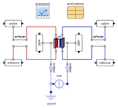
Figure 3: Diagram of the test stand model.
Licensed by the Hawaii Natural Energy Institute under the Modelica License 2
Copyright © 2007–2014, Hawaii Natural Energy Institute and Georgia Tech Research Corporation.
This Modelica package is free software and the use is completely at your own risk; it can be redistributed and/or modified under the terms of the Modelica License 2. For license conditions (including the disclaimer of warranty) see FCSys.UsersGuide.License or visit http://www.modelica.org/licenses/ModelicaLicense2.
Extends from Modelica.Icons.Package (Icon for standard packages).Package Content
| Name | Description |
|---|---|
| User's Guide | |
| Imperative models (inputs and outputs only) | |
| Models to specify and measure operating conditions | |
| Combinations of regions (e.g., cells) | |
| 3D arrays of discrete, interconnected subregions | |
| Control volumes with multi-species transfer and storage | |
| Mixtures of species | |
| Dynamic models of chemical species | |
| Chemical reactions and related models | |
| Data and functions to correlate physical properties | |
| Declarative and imperative interfaces | |
| Constants and units of physical measure | |
| Types to represent physical values | |
| General supporting functions | |
| Icons to annotate and represent classes |