FCSys
![]()
Table of Contents
- User's Guide
- Blocks
- Conditions
- Assemblies
- Regions
- Subregions
- Phases
- Species
- Chemistry
- Connectors
- Characteristics
- Units
- Quantities
- Utilities
- Icons
Download
- Latest: v0.2.6 (2014-01-25)
FCSys.Assemblies.Cells.Examples
ExamplesInformation
Extends from Modelica.Icons.ExamplesPackage (Icon for packages containing runnable examples).Package Content
| Name | Description |
|---|---|
| Fuel cell test conditions | |
| Simulate the fuel cell under prescribed conditions | |
| Simulate the fuel cell under prescribed conditions, with cyclical load | |
| Simulate the simple fuel cell model under prescribed conditions | |
| Wrapper for linear analysis of the fuel cell under prescribed conditions | |
| Simulate the fuel cell with multiple segments in the y direction | |
| Simulate the fuel cell with multiple segments in the y direction, with fixed flow rate | |
| Simulate the fuel cell with multiple segments in the y direction, with fixed flow rate |
 FCSys.Assemblies.Cells.Examples.TestConditions
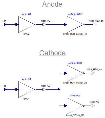
Fuel cell test conditions
Information
Some conditions are taken from the outer environment model. In particular,
environment.Tis used as the initial temperature throughout the cell, the temperature at each inlet, and the exterior temperature of each end plate in the yz plane.environment.pis used as the initial pressure throughout the cell and the pressure at each outlet.environment.RHis used as the initial relative humidity throughout the cell.environment.psi_O2_dryis used as the dry-gas concentration of O2 at the cathode inlet.
Parameters
| Type | Name | Default | Description |
|---|---|---|---|
| Anode | |||
| RealInputInternal | I_an | U.A | Equivalent current [N/T] |
| NumberAbsolute | anRH | 0.8 | Relative humidity (at inlet) [1] |
| Cathode | |||
| RealInputInternal | I_ca | U.A | Equivalent current [N/T] |
| NumberAbsolute | caRH | 0.5 | Relative humidity (at inlet) [1] |
Connectors
| Type | Name | Description |
|---|---|---|
| output RealOutputInternal | Ndot_H2O_an | Rate of supply of H2O into the anode [N/T] |
| output RealOutputInternal | Ndot_O2 | Rate of supply of O2 [N/T] |
| output RealOutputInternal | Ndot_H2O_ca | Rate of supply of H2O into the cathode [N/T] |
| output RealOutputInternal | Ndot_N2 | Rate of supply of N2 [N/T] |
| output RealOutputInternal | Ndot_H2 | Rate of supply of H2 [N/T] |
| Anode | ||
| input RealInputInternal | I_an | Equivalent current [N/T] |
| Cathode | ||
| input RealInputInternal | I_ca | Equivalent current [N/T] |
Modelica definition
model TestConditions "Fuel cell test conditions"
  extends FCSys.Icons.Record;
  // Note:  This isn't a record because it contains time-varying variables.
  import FCSys.Characteristics.H2O.p_sat;

  final parameter Q.NumberAbsolute psi_sat=environment.p_sat/environment.p
    "Mole fraction of H2O at saturation";

  // Anode
  Connectors.RealInputInternal I_an(unit="N/T") = U.A "Equivalent current";
  parameter Q.NumberAbsolute anRH(
    displayUnit="%",
    max=1) = 0.8 "Relative humidity (at inlet)";
  final parameter Q.NumberAbsolute psi_H2O_an=anRH*psi_sat
    "Mole fraction of H2O at the anode inlet";
  final parameter Q.NumberAbsolute psi_H2=1 - psi_H2O_an
    "Mole fraction of H2 at the anode inlet";

  // Cathode
  Connectors.RealInputInternal I_ca(unit="N/T") = U.A "Equivalent current";
  parameter Q.NumberAbsolute caRH(
    displayUnit="%",
    max=1) = 0.5 "Relative humidity (at inlet)";
  final parameter Q.NumberAbsolute psi_H2O_ca=caRH*psi_sat
    "Mole fraction of H2O at the cathode inlet";
  final parameter Q.NumberAbsolute psi_O2=environment.psi_O2_dry*(1 -
      psi_H2O_ca) "Mole fraction of O2 at the cathode inlet";
  final parameter Q.NumberAbsolute psi_N2=(1 - environment.psi_O2_dry)*(1 -
      psi_H2O_ca) "Mole fraction of N2 at the cathode inlet";

  Modelica.Blocks.Math.Gain stoichH2(k=1/2);
  Modelica.Blocks.Math.Gain anStoichH2O(k=psi_H2O_an/psi_H2);
  Modelica.Blocks.Math.Gain stoichO2(k=1/4);
  Modelica.Blocks.Math.Gain caStoichH2O(k=psi_H2O_ca/psi_O2);
  Modelica.Blocks.Math.Gain stoichN2(k=psi_N2/psi_O2);

  Connectors.RealOutputInternal Ndot_H2O_an(unit="N/T")
    "Rate of supply of H2O into the anode";
  Connectors.RealOutputInternal Ndot_O2(unit="N/T") "Rate of supply of O2";
  Connectors.RealOutputInternal Ndot_H2O_ca(unit="N/T")
    "Rate of supply of H2O into the cathode";
  Connectors.RealOutputInternal Ndot_N2(unit="N/T") "Rate of supply of N2";
  Connectors.RealOutputInternal Ndot_H2(unit="N/T") "Rate of supply of H2";

protected
  outer Conditions.Environment environment "Environmental conditions";

equation
  connect(stoichH2.y, Ndot_H2);
  connect(Ndot_H2, anStoichH2O.u);
  connect(anStoichH2O.y, Ndot_H2O_an);
  connect(stoichO2.y, Ndot_O2);
  connect(Ndot_O2, caStoichH2O.u);
  connect(caStoichH2O.y, Ndot_H2O_ca);
  connect(stoichN2.y, Ndot_N2);
  connect(stoichN2.u, Ndot_O2);
  connect(I_an, stoichH2.u);
  connect(I_ca, stoichO2.u);
end TestConditions;
 FCSys.Assemblies.Cells.Examples.TestStand
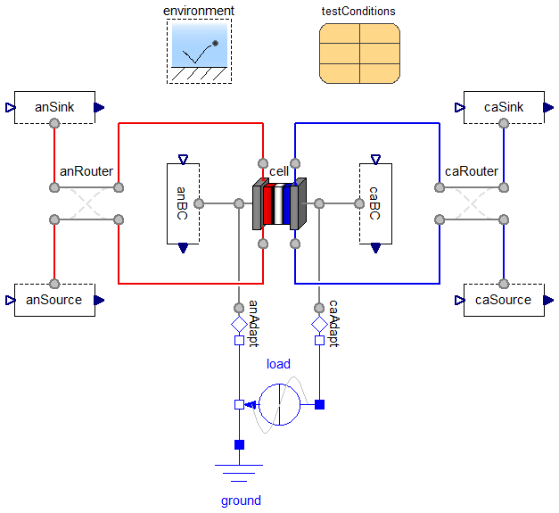
Simulate the fuel cell under prescribed conditions

Information
Please see TestConditions regarding how the properties of the environment are used.
To run the cell with pure O2 in the cathode (no N2), set environment.psi_O2_dry to 100%.
Assumptions:
- The outer surface of each end plate has uniform temperature in the yz plane.
- No heat is conducted from the rest of the cell hardware.
- All electronic current passes through the first segment (index
[1, 1]) of each end plate in the yz plane. - There is no shear force on the fluid at either outlet.
- The pressure of each gas species is uniform over each inlet.
- The volumetric flow rates of the gas species are equal at each outlet, where the volumetric flow rate is approximated using the current at the outlet and the density of the gas within the last segment of the cell.
- The outlet pressure is applied to the gas mixture by Dalton's law (additivity of pressure).
- At the outlet, the liquid has the same pressure as the gas (Amagat's law).
- There is no thermal conduction across either outlet.
Parameters
| Type | Name | Default | Description |
|---|---|---|---|
| Cell | cell | redeclare Cell cell(inclN2=e… | Fuel cell |
| RampCurrent | load | redeclare Modelica.Electrica… | Electrical load |
| Router | anRouter[cell.anFP.n_x, cell.n_z] | Switch to route the anode for reverse flow | |
| Router | caRouter[cell.anFP.n_x, cell.n_z] | Switch to route the cathode for reverse flow | |
| TestConditions | testConditions | Test conditions |
Modelica definition
model TestStand "Simulate the fuel cell under prescribed conditions"
  import 'Datae-' = FCSys.Characteristics.'e-'.Graphite;
  import DataH2 = FCSys.Characteristics.H2.Gas;
  import DataH2O = FCSys.Characteristics.H2O.Gas;
  import DataO2 = FCSys.Characteristics.O2.Gas;
  import average = FCSys.Utilities.Means.arithmetic;
  extends Modelica.Icons.Example;

  // Aliases
  Q.Current zI "Electrical current";

  // Auxiliary variables (for analysis)
  output Q.Potential w=load.v*U.V "Potential";
  output Q.CurrentAreic J=zI/cell.caFP.A[Axis.x] "Current density";
  output Q.Number J_Apercm2=J*U.cm^2/U.A "Current density, in A/cm2";
  output Q.PressureAbsolute p_an_in=average(average(anSource.gas.H2.boundary.p +
      anSource.gas.H2O.boundary.p)) if environment.analysis
    "Total pressure at the anode inlet";
  output Q.PressureAbsolute p_ca_in=average(average(caSource.gas.H2O.boundary.p +
      p_N2_in + caSource.gas.O2.boundary.p)) if environment.analysis
    "Total pressure at the cathode inlet";
  output Q.Pressure Deltap_an=environment.p - p_an_in if environment.analysis
    "Pressure difference down the anode channel";
  output Q.Pressure Deltap_ca=environment.p - p_ca_in if environment.analysis
    "Pressure difference down the cathode channel";
  output Q.Potential Deltaw_O2=(DataO2.g(caSource[1, 1].gas.O2.boundary.T,
      caSource[1, 1].gas.O2.boundary.p) - cell.caCL.subregions[1, 1, 1].gas.O2.g)
      /4 if environment.analysis "Voltage loss due to O2 supply";
  output Q.Potential Deltaw_H2O=(DataH2O.g(caSource[1, 1].gas.H2O.boundary.T,
      caSource[1, 1].gas.H2O.boundary.p) - cell.caCL.subregions[1, 1, 1].gas.H2O.g)
      /2 if environment.analysis "Voltage loss due to H2O removal";
  output Q.Potential Deltaw_H2=(DataH2.g(anSource[1, 1].gas.H2.boundary.T,
      anSource[1, 1].gas.H2.boundary.p) - cell.anCL.subregions[1, 1, 1].gas.H2.g)
      /2 if environment.analysis "Voltage loss due to H2 supply";
  output Q.Potential 'Deltaw_e-'=cell.caFP.subregions[1, 1, 1].graphite.'e-'.g_boundaries[
      1, Side.p] - cell.caCL.subregions[1, 1, 1].graphite.'e-'.g + cell.anCL.subregions[
      1, 1, 1].graphite.'e-'.g - cell.anFP.subregions[1, 1, 1].graphite.'e-'.g_boundaries[
      1, Side.n] if environment.analysis "Voltage loss due to e- transport";
  output Q.Potential 'Deltaw_H+'=cell.anCL.subregions[1, 1, 1].ionomer.'H+'.g -
      cell.caCL.subregions[1, 1, 1].ionomer.'H+'.g if environment.analysis
    "Voltage loss due to H+ transport";
  output Q.Potential Deltaw_an=cell.anCL.subregions[1, 1, 1].graphite.
      'e-Transfer'.Deltag if environment.analysis "Anode overpotential";
  output Q.Potential Deltaw_ca=-cell.caCL.subregions[1, 1, 1].graphite.
      'e-Transfer'.Deltag if environment.analysis "Cathode overpotential";

  replaceable Cell cell(inclN2=environment.psi_O2_dry < 1 - Modelica.Constants.eps)
    constrainedby FCSys.Icons.Cell "Fuel cell";

  // Conditions
  Conditions.ByConnector.BoundaryBus.Single.Sink anBC[cell.n_y, cell.n_z](each
      graphite('inclC+'=true, redeclare Conditions.ByConnector.ThermalDiffusive.Single.Temperature
        'C+'(set(y=environment.T))))
    "Boundary condition for the anode end plate, except electrical";

  Conditions.ByConnector.BoundaryBus.Single.Source anSource[cell.anFP.n_x, cell.n_z]
    (each gas(
      inclH2=true,
      inclH2O=true,
      H2(materialSet(y=-testConditions.Ndot_H2), thermalSet(y=environment.T)),
      H2O(materialSet(y=-testConditions.Ndot_H2O_an), thermalSet(y=environment.T))))
    "Source for the anode reactant stream";

  Conditions.ByConnector.BoundaryBus.Single.Sink anSink[cell.anFP.n_x, cell.n_z]
    (gas(
      each inclH2=true,
      each inclH2O=true,
      H2(redeclare each function materialSpec = Conditions.ByConnector.Boundary.Single.Material.current,
          materialSet(y=anSink.gas.H2O.boundary.Ndot .* cell.anFP.subregions[:,
              cell.n_y, :].gas.H2O.v ./ cell.anFP.subregions[:, cell.n_y, :].gas.H2.v)),

      H2O(materialSet(y=fill(
              environment.p,
              cell.anFP.n_x,
              cell.n_z) - anSink.gas.H2.p))), each liquid(inclH2O=cell.inclLiq,
        H2O(materialSet(y=environment.p))))
    "Sink for the anode reactant stream";

  Conditions.ByConnector.BoundaryBus.Single.Source caBC[cell.n_y, cell.n_z](
      each graphite('inclC+'=true,'C+'(set(y=environment.T))))
    "Boundary condition for the cathode end plate, except electrical";

  Conditions.ByConnector.BoundaryBus.Single.Source caSource[cell.caFP.n_x, cell.n_z]
    (gas(
      each inclH2O=true,
      each inclN2=cell.inclN2,
      each inclO2=true,
      each H2O(materialSet(y=-testConditions.Ndot_H2O_ca), thermalSet(y=
              environment.T)),
      N2(
        each materialSet(y=-testConditions.Ndot_N2),
        each thermalSet(y=environment.T),
        redeclare function materialMeas = Conditions.ByConnector.Boundary.Single.Material.pressure),

      each O2(materialSet(y=-testConditions.Ndot_O2),thermalSet(y=environment.T))))
    "Source for the cathode reactant stream";

  Conditions.ByConnector.BoundaryBus.Single.Sink caSink[cell.caFP.n_x, cell.n_z]
    (gas(
      each inclO2=true,
      each inclN2=cell.inclN2,
      each inclH2O=true,
      H2O(materialSet(y=fill(
              environment.p,
              cell.caFP.n_x,
              cell.n_z) - p_N2_out - caSink.gas.O2.p)),
      N2(
        redeclare function materialSpec = Conditions.ByConnector.Boundary.Single.Material.current,

        materialSet(y=caSink.gas.H2O.boundary.Ndot .* cell.caFP.subregions[:,
              cell.n_y, :].gas.H2O.v ./ cell.caFP.subregions[:, cell.n_y, :].gas.N2.v),

        redeclare function materialMeas = Conditions.ByConnector.Boundary.Single.Material.pressure),

      O2(redeclare function materialSpec = Conditions.ByConnector.Boundary.Single.Material.current,
          materialSet(y=caSink.gas.H2O.boundary.Ndot .* cell.caFP.subregions[:,
              cell.n_y, :].gas.H2O.v ./ cell.caFP.subregions[:, cell.n_y, :].gas.O2.v))),
      each liquid(inclH2O=cell.inclLiq, H2O(materialSet(y=environment.p))))
    "Sink for the cathode reactant stream";

  inner Conditions.Environment environment(
    a={0,0,0},
    RH=testConditions.anRH,
    T=333.13*U.K,
    p=U.from_kPag(48.3)) "Environmental conditions";

  replaceable Modelica.Electrical.Analog.Sources.RampCurrent load(
    offset=0.0001,
    startTime=180,
    I=150,
    duration=36000) constrainedby Modelica.Electrical.Analog.Interfaces.TwoPin
    "Electrical load";
  Modelica.Electrical.Analog.Basic.Ground ground;
  Conditions.Adapters.MSL.Electronic anAdapt
    "Interface with Modelica.Electrical on the anode side";
  Conditions.Adapters.MSL.Electronic caAdapt
    "Interface with Modelica.Electrical on the cathode side";

  Conditions.Router anRouter[cell.anFP.n_x, cell.n_z]
    "Switch to route the anode for reverse flow";
  Conditions.Router caRouter[cell.anFP.n_x, cell.n_z]
    "Switch to route the cathode for reverse flow";

  TestConditions testConditions(I_ca=2*zI, I_an=1.5*zI) "Test conditions";

protected
  Connectors.RealInput p_N2_in[cell.caFP.n_x, cell.n_z](each unit="M/(L.T2)")
    "Pressure of N2 at inlet";
  Connectors.RealInput p_N2_out[cell.caFP.n_x, cell.n_z](each unit="M/(L.T2)")
    "Pressure of N2 at outlet";

equation
  // Aliases
  zI = load.i*U.A;

  // Nitrogen pressures (since N2 is conditionally included)
  connect(p_N2_in, caSource.gas.N2.materialOut.y) "Not shown in diagram";
  connect(p_N2_out, caSink.gas.N2.materialOut.y) "Not shown in diagram";
  if not cell.inclN2 then
    p_N2_in = zeros(cell.caFP.n_x, cell.n_y);
    p_N2_out = zeros(cell.caFP.n_x, cell.n_y);
  end if;

  connect(cell.an[1, 1], anAdapt.boundary);
  connect(cell.ca[1, 1], caAdapt.boundary);
  connect(cell.an, anBC.boundary);
  connect(cell.ca, caBC.boundary);
  connect(anRouter.positive2, anSink.boundary);
  connect(anRouter.positive1, anSource.boundary);
  connect(cell.anPositive, anRouter.negative2);
  connect(cell.anNegative, anRouter.negative1);
  connect(caSink.boundary, caRouter.negative2);
  connect(caSource.boundary, caRouter.negative1);
  connect(caRouter.positive2, cell.caPositive);
  connect(caRouter.positive1, cell.caNegative);
  connect(anAdapt.pin, load.n);
  connect(load.n, ground.p);
  connect(caAdapt.pin, load.p);
end TestStand;
FCSys.Assemblies.Cells.Examples.TestStandCycle
Simulate the fuel cell under prescribed conditions, with cyclical load
Information
Extends from TestStand (Simulate the fuel cell under prescribed conditions).
Parameters
| Type | Name | Default | Description |
|---|---|---|---|
| Router | anRouter[cell.anFP.n_x, cell.n_z] | Switch to route the anode for reverse flow | |
| Router | caRouter[cell.anFP.n_x, cell.n_z] | Switch to route the cathode for reverse flow |
Modelica definition
model TestStandCycle
  "Simulate the fuel cell under prescribed conditions, with cyclical load"
  extends TestStand(
    cell(
      anCL(subregions(graphite(each inclDL=true, 'e-Transfer'(each fromI=false)),
            ionomer(H2O(each lambda_IC=13.53)))),
      PEM(subregions(ionomer(H2O(each lambda_IC=13.53)))),
      caCL(subregions(graphite(each inclDL=true, 'e-Transfer'(each fromI=false)),
            ionomer(H2O(each lambda_IC=13.53))))),
    redeclare Modelica.Electrical.Analog.Sources.SineCurrent load(
      freqHz=0.3,
      I=7,
      offset=4),
    testConditions(I_an=15*U.A, I_ca=20*U.A));

end TestStandCycle;
FCSys.Assemblies.Cells.Examples.TestStandSimple
Simulate the simple fuel cell model under prescribed conditions

Information
Extends from TestStand (Simulate the fuel cell under prescribed conditions).
Parameters
| Type | Name | Default | Description |
|---|---|---|---|
| Potential | Deltaw_O2 | (DataO2.g(caSource[1, 1].gas… | Voltage loss due to O2 supply [L2.M/(N.T2)] |
| Potential | Deltaw_H2O | (DataH2O.g(caSource[1, 1].ga… | Voltage loss due to H2O removal [L2.M/(N.T2)] |
| Potential | Deltaw_H2 | (DataH2.g(anSource[1, 1].gas… | Voltage loss due to H2 supply [L2.M/(N.T2)] |
| Potential | 'Deltaw_e-' | cell.caFP.subregions[1, 1, 1… | Voltage loss due to e- transport [L2.M/(N.T2)] |
| Potential | 'Deltaw_H+' | cell.anCGDL.subregions[1, 1,… | Voltage loss due to H+ transport [L2.M/(N.T2)] |
| Potential | Deltaw_an | cell.anCGDL.subregions[1, 1,… | Anode overpotential [L2.M/(N.T2)] |
| Potential | Deltaw_ca | -cell.caCGDL.subregions[1, 1… | Cathode overpotential [L2.M/(N.T2)] |
| RampCurrent | load | redeclare Modelica.Electrica… | Electrical load |
| Router | anRouter[cell.anFP.n_x, cell.n_z] | Switch to route the anode for reverse flow | |
| Router | caRouter[cell.anFP.n_x, cell.n_z] | Switch to route the cathode for reverse flow | |
| TestConditions | testConditions | Test conditions |
Modelica definition
model TestStandSimple
  "Simulate the simple fuel cell model under prescribed conditions"

  import DataH2 = FCSys.Characteristics.H2.Gas;
  import DataH2O = FCSys.Characteristics.H2O.Gas;
  import DataO2 = FCSys.Characteristics.O2.Gas;

  extends TestStand(
    redeclare SimpleCell cell(inclN2=environment.psi_O2_dry < 1 - Modelica.Constants.eps),

    Deltaw_O2=(DataO2.g(caSource[1, 1].gas.O2.boundary.T, caSource[1, 1].gas.O2.boundary.p)
         - cell.caCGDL.subregions[1, 1, 1].gas.O2.g)/4,
    Deltaw_H2O=(DataH2O.g(caSource[1, 1].gas.H2O.boundary.T, caSource[1, 1].gas.H2O.boundary.p)
         - cell.caCGDL.subregions[1, 1, 1].gas.H2O.g)/2,
    Deltaw_H2=(DataH2.g(anSource[1, 1].gas.H2.boundary.T, anSource[1, 1].gas.H2.boundary.p)
         - cell.anCGDL.subregions[1, 1, 1].gas.H2.g)/2,
    'Deltaw_e-'=cell.caFP.subregions[1, 1, 1].graphite.'e-'.g_boundaries[1,
        Side.p] - cell.caCGDL.subregions[1, 1, 1].graphite.'e-'.g + cell.anCGDL.subregions[
        1, 1, 1].graphite.'e-'.g - cell.anFP.subregions[1, 1, 1].graphite.'e-'.g_boundaries[
        1, Side.n],
    'Deltaw_H+'=cell.anCGDL.subregions[1, 1, 1].ionomer.'H+'.g - cell.caCGDL.subregions[
        1, 1, 1].ionomer.'H+'.g,
    Deltaw_an=cell.anCGDL.subregions[1, 1, 1].graphite.'e-Transfer'.Deltag,
    Deltaw_ca=-cell.caCGDL.subregions[1, 1, 1].graphite.'e-Transfer'.Deltag);

end TestStandSimple;
FCSys.Assemblies.Cells.Examples.TestStandLinearize
Wrapper for linear analysis of the fuel cell under prescribed conditions

Information
Extends from TestStand (Simulate the fuel cell under prescribed conditions).
Parameters
| Type | Name | Default | Description |
|---|---|---|---|
| Router | anRouter[cell.anFP.n_x, cell.n_z] | Switch to route the anode for reverse flow | |
| Router | caRouter[cell.anFP.n_x, cell.n_z] | Switch to route the cathode for reverse flow | |
| TestConditions | testConditions | Test conditions |
Modelica definition
model TestStandLinearize
  "Wrapper for linear analysis of the fuel cell under prescribed conditions"

  extends TestStand(
    environment(analysis=false),
    cell(anCL(subregions(graphite(each inclDL=true, 'e-Transfer'(each fromI=false)))),
        caCL(subregions(graphite(each inclDL=true, 'e-Transfer'(each fromI=false))))),

    redeclare Modelica.Electrical.Analog.Sources.SignalCurrent load(i(
        start=50,
        stateSelect=StateSelect.always,
        fixed=true)));

  output Modelica.SIunits.Voltage w_V=load.v "Potential in volts";

equation
  der(load.i) = 0 "Current is a dummy state -- only for linear analysis.";

end TestStandLinearize;
FCSys.Assemblies.Cells.Examples.TestStandSegmented
Simulate the fuel cell with multiple segments in the y direction

Information
Extends from TestStand (Simulate the fuel cell under prescribed conditions).
Parameters
| Type | Name | Default | Description |
|---|---|---|---|
| RampCurrent | load | redeclare Modelica.Electrica… | Electrical load |
| Router | anRouter[cell.anFP.n_x, cell.n_z] | Switch to route the anode for reverse flow | |
| Router | caRouter[cell.anFP.n_x, cell.n_z] | Switch to route the cathode for reverse flow | |
| TestConditions | testConditions | Test conditions | |
| Geometry | |||
| Integer | n_y | 6 | Number of segments in the y direction |
Modelica definition
model TestStandSegmented
  "Simulate the fuel cell with multiple segments in the y direction"

  parameter Integer n_y=6 "Number of segments in the y direction";
  import Modelica.Constants.inf;

  extends TestStand(cell(
      inclLiq=false,
      L_y=fill(8*U.cm/n_y, n_y),
      anGDL(epsilon=0.45),
      caGDL(epsilon=0.45)));

end TestStandSegmented;
FCSys.Assemblies.Cells.Examples.TestStandFixedFlow
Simulate the fuel cell with multiple segments in the y direction, with fixed flow rate

Information
Extends from TestStand (Simulate the fuel cell under prescribed conditions).
Parameters
| Type | Name | Default | Description |
|---|---|---|---|
| Cell | cell | redeclare Cell cell(inclN2=e… | Fuel cell |
| Router | anRouter[cell.anFP.n_x, cell.n_z] | Switch to route the anode for reverse flow | |
| Router | caRouter[cell.anFP.n_x, cell.n_z] | Switch to route the cathode for reverse flow |
Modelica definition
model TestStandFixedFlow
  "Simulate the fuel cell with multiple segments in the y direction, with fixed flow rate"
  extends TestStand(testConditions(I_an=anFlowSet.y, I_ca=caFlowSet.y), load(
        startTime=120));
  Modelica.Blocks.Sources.Ramp anFlowSet(
    height=120*U.A,
    duration=120,
    offset=0.1*U.mA,
    startTime=60) "Specify the equivalent current of the anode supplies";
  Modelica.Blocks.Sources.Ramp caFlowSet(
    height=160*U.A,
    duration=120,
    offset=0.1*U.mA,
    startTime=60) "Specify the equivalent current of the cathode supplies";
end TestStandFixedFlow;
FCSys.Assemblies.Cells.Examples.TestStandFixedFlowSegmented
Simulate the fuel cell with multiple segments in the y direction, with fixed flow rate
Information
Extends from TestStandFixedFlow (Simulate the fuel cell with multiple segments in the y direction, with fixed flow rate).
Parameters
| Type | Name | Default | Description |
|---|---|---|---|
| Router | anRouter[cell.anFP.n_x, cell.n_z] | Switch to route the anode for reverse flow | |
| Router | caRouter[cell.anFP.n_x, cell.n_z] | Switch to route the cathode for reverse flow | |
| Geometry | |||
| Integer | n_y | 6 | Number of segments in the y direction |
Modelica definition
model TestStandFixedFlowSegmented
  "Simulate the fuel cell with multiple segments in the y direction, with fixed flow rate"
  parameter Integer n_y=6 "Number of segments in the y direction";

  extends TestStandFixedFlow(
    cell(
      inclLiq=false,
      L_y=fill(8*U.cm/n_y, n_y),
      anGDL(epsilon=0.45),
      caGDL(epsilon=0.45)),
    testConditions(I_an=anFlowSet.y, I_ca=caFlowSet.y),
    caFlowSet(startTime=0),
    anFlowSet(startTime=0),
    load(startTime=0));

end TestStandFixedFlowSegmented;