FCSys.Regions.CaFPs
Cathode flow platesInformation
Extends from Modelica.Icons.Package (Icon for standard packages).Package Content
| Name | Description |
|---|---|
| Cathode flow plate |
 FCSys.Regions.CaFPs.CaFP
Cathode flow plate

Information
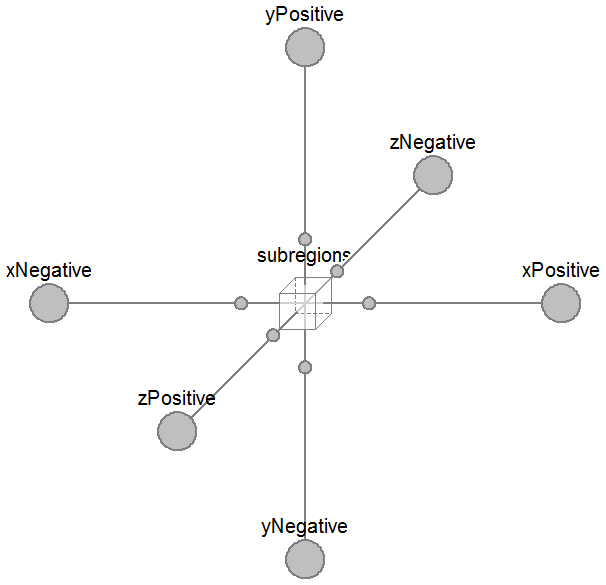
This model represents the cathode flow plate of a PEMFC. It is identical to the anode flow plate except for the included species, the default length of the channel, and the fraction of the volume for the fluid (ε). For more information, please see the anFP model.
Extends from Region (Base model for a 3D array of subregions).
Parameters
| Type | Name | Default | Description |
|---|---|---|---|
| replaceable model Subregion | FCSys.Subregions.SubregionNo… | Base subregion model | |
| Length | D | 0.815*U.mm | Hydraulic diameter of the channel [L] |
| Length | L_channel | 106.4*U.cm | Length of the channel [L] |
| Geometry | |||
| Length | L_x[:] | {10}*U.mm | Lengths along the x axis [L] |
| Length | L_y[:] | {8}*U.cm | Lengths along the y axis [L] |
| Length | L_z[:] | {6.25}*U.cm | Lengths across the z axis [L] |
| NumberAbsolute | epsilon | 0.0423 | Fraction of volume for the fluid [1] |
| Assumptions | |||
| Included transport axes | |||
| Boolean | inclTransX | true | X |
| Boolean | inclTransY | true | Y |
| Boolean | inclTransZ | false | Z |
Connectors
| Type | Name | Description |
|---|---|---|
| replaceable model Subregion | Base subregion model | |
| BoundaryBus | xNegative[n_y, n_z] | Negative boundary along the x axis |
| BoundaryBus | xPositive[n_y, n_z] | Positive boundary along the x axis |
| BoundaryBus | yNegative[n_x, n_z] | Negative boundary along the y axis |
| BoundaryBus | yPositive[n_x, n_z] | Positive boundary along the y axis |
| BoundaryBus | zNegative[n_x, n_y] | Negative boundary along the z axis |
| BoundaryBus | zPositive[n_x, n_y] | Positive boundary along the z axis |
Modelica definition
model CaFP "Cathode flow plate"
  import Modelica.Constants.inf;
  // extends FCSys.Icons.Names.Top4;

  extends Region(
    L_x={10}*U.mm,
    L_y={8}*U.cm,
    L_z={6.25}*U.cm,
    final inclTransX=true,
    final inclTransY=true,
    inclTransZ=false,
    redeclare replaceable model Subregion = FCSys.Subregions.SubregionNoIonomer
        (
        common(k_Phi={1e7,inf,1e7},k_Q=1e5),
        gas(
          common(k_Phi={inf,inf,inf}),
          H2O_N2(k_Phi={inf,inf,inf}),
          H2O_O2(k_Phi={inf,inf,inf}),
          N2_O2(k_Phi={inf,inf,inf}),
          k={0.17*epsilon,Lstar/n_y,n_y/Lstar},
          inclH2O=true,
          inclN2=true,
          inclO2=true,
          H2O(
            upstreamX=false,
            Nu_Phi={4,16*A[Axis.z]*epsilon/D^2,4},
            final zeta=0,
            T(stateSelect=StateSelect.always)),
          N2(
            upstreamX=false,
            Nu_Phi={4,16*A[Axis.z]*epsilon/D^2,4},
            final zeta=0,
            initEnergy=Init.none,
            I(each stateSelect=StateSelect.always, each fixed=true)),
          O2(
            upstreamX=false,
            Nu_Phi={4,16*A[Axis.z]*epsilon/D^2,4},
            final zeta=0,
            initEnergy=Init.none)),
        graphite(
          'inclC+'=true,
          'incle-'=true,
          'C+'(theta=U.m*U.K/(95*U.W),epsilon=1 - epsilon),
          'e-'(sigma=U.S/(1.470e-3*U.cm))),
        liquid(
          k={0.17*epsilon,Lstar/n_y,n_y/Lstar},
          inclH2O=true,
          H2O(
            upstreamX=false,
            Nu_Phi={4,16*A[Axis.z]*epsilon/D^2,4},
            epsilon_IC=1e-5,
            N0=0.1*U.C))));

  parameter Q.NumberAbsolute epsilon(nominal=1) = 0.0423
    "Fraction of volume for the fluid";

  parameter Q.Length D=0.815*U.mm "Hydraulic diameter of the channel";

  parameter Q.Length L_channel=106.4*U.cm "Length of the channel";

protected
  final parameter Q.NumberAbsolute Lstar=L_channel/L[Axis.y]
    "Ratio of the length of the channel to the length of the layer in the y direction";

  Q.Velocity phi_states_H2O[:, :, :](
    each stateSelect=StateSelect.always,
    each start=0,
    each fixed=true) = subregions[:, 2:n_y, :].gas.H2O.phi[2] if n_y > 1
    "Forced states for H2O";
  Q.Velocity phi_states_O2[:, :, :](
    each stateSelect=StateSelect.always,
    each start=0,
    each fixed=true) = subregions[:, 2:n_y, :].gas.O2.phi[2] if n_y > 1
    "Forced states for O2";
  // Note:  These variables avoid dynamic state selection in Dymola 2014.

  outer Conditions.Environment environment "Environmental conditions";

  // See AnFPs.AnFP for data on additional materials.

end CaFP;